| |
 What is
a PA System? What is
a PA System? |
| “Public address” (PA) refers to
the act of speaking to the public. A PA system is therefore
a system that aids in speaking to a large number of people to
deliver information to them in one direction. An amplifier,
audio device, broadcasting device or microphones are all parts
of a PA system with which a speaker uses to deliver information
to many people both aurally and visually. |
| |
| Connecting
a PA amplifier and speakers (installed with matching transformers)
|
| Found on the output (speaker connectors)
of a PA amp are low impedance (4Ω, 8Ω, and 16Ω) and high impedance
(100V, 75V) connectors. Speakers used in PA amplifiers are often
connected to high-impedance connectors (installed with matching
transformers) because it allows the simultaneous use of several
speakers and connects speakers that are far away from the amplifier.
|
| |
| Installation
chart |
 |
 shown
above, connect speakers to an amplifier in parallel. (Use high-impedance
speakers.) shown
above, connect speakers to an amplifier in parallel. (Use high-impedance
speakers.) |
| way that
the rated output (W) of the amplifier is identical to the allowed
input (W) of the speakers. |
| shown
in the figure above, use four 25W speakers = 25 x 4 = 100W (a
total allowed input of 100W) |
| Selecting
an amplifier = an amplifier with 100W of rated power. |
|
| As shown above, having several or
dozens of speakers connected to an amplifier makes it difficult
to calculate the accumulated impedance of the speakers. The
easiest way to calculate the total impedance is to sum up all
the rated inputs (W) printed on each speaker, and select a PA
amplifier that has the same output. |
 |
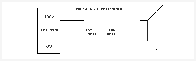
| Matching
Transformer |
| A PA amplifier often uses high impedance
(100V line) on the speaker connectors. However, speakers are
produced at a low impedance (4Ω, 8Ω, and 16Ω), and directly
connecting them to the amplifier will cause over-voltage to
damage and make them unusable. The first phase of a matching
transformer is connected to the speaker connectors (100V) of
the PA amplifier to take high voltage, whereas the second phase
of the matching transformer outputs the high voltage to low
voltage and delivers it to the speakers, thus protecting the
speakers. The PA amplifier is designed with such a high voltage
(100V) to reduce the output voltage loss along the line when
it is connected to speakers that are located far away and to
enable the use of dozens of speakers. |
 |
| In general, a PA speaker
is installed with a matching transformer, which is called a
high-impedance speaker. On the other hand, those driver units
or other speakers that are not installed with a matching transformer
are called low-impedance speakers, which require a separate
matching transformer. |
| |
| High
impedance of speakers and output calculation table |
| Output |
Impedance |
Output |
Impedance |
Output |
Impedance |
| 0.1W |
100KΩ |
10W |
1KΩ |
40W |
250Ω |
| 0.5W |
20KΩ |
15W |
667Ω |
50W |
200Ω |
| 1W |
10KΩ |
20W |
500Ω |
75W |
133Ω |
| 2W |
5KΩ |
25W |
400Ω |
100W |
100Ω |
| 3W |
3.33KΩ |
30W |
333Ω |
150W |
66.7Ω |
| 5W |
2KΩ |
35W |
286Ω |
200W |
50Ω |
|
| (100V
plan) P = E x E / Z = 100x100 / Z = 10,000 / Z |
| P : Power(W), Z : Impedance(Ω),
E : 100V(Designed voltage of a general-use amplifier) |
| |
|
| Connecting
low-impedance speakers (4Ω, 8Ω, and 16Ω) to an amplifier |
 Make the impedance
of the amplifier output identical to that of a speaker. Make the impedance
of the amplifier output identical to that of a speaker.
(e.g., 8Ω Amplifier = 8Ω Speaker)
(When using more than one speaker, the accumulated
impedance should be identical to that of the amplifier’s output.) |
Make the allowable
input of speakers either identical to or slightly bigger than
the rated output of the
amplifier.
(e.g., for a 100W rated amplifier, make the accumulated allowable
input of speakers either identical to or greater than
100W) |
| |
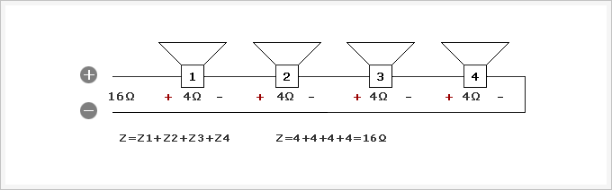
| Serial
connection: sum up the impedance of all speakers |
 |
| |
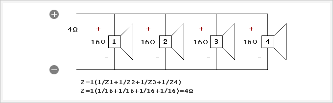
Parallel
connection: if all speakers have similar impedance (speaker
impedance ÷ number of speakers)
= (16÷4=4Ω) |
 |
| |
| Serial-parallel
connection |
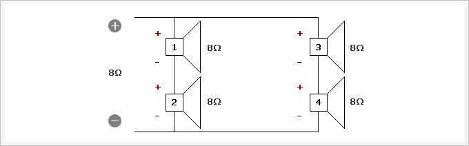 |
| (1) Serial impedance Z1= 1+2 , Z2
=3+4 (Z1= 8+8=16, Z2=8+8=16) |
(2) Parallel impedance 16÷2=8Ω (in
case when speakers have a similar impedance)
| As shown above, connecting
speakers with impedance (4Ω, 8Ω, and 16Ω) can be performed
in three ways. The serial and parallel methods are appropriate
in connecting from two to four speakers, and when connecting
more than four speakers, the use of the serial/parallel
method is advised. Please make sure to always use an even
number of speakers, with the same impedance, output, and
manufacturer. |
| Speakers can be protected
from damage when their rated allowable input (W) is larger
than the rated output of an amplifier. To use a 100W rated
amplifier, the accumulated allowable input of the total
number of speakers to be connected should be more than
100W. |
|
| Impedance
relationship between an amplifier and a speaker |
| Impedance |
Remarks |
| Amplifier |
Speaker |
| 8Ω |
8Ω |
Amplifier = Speaker
The designed output of the amplifier can be used. |
| 8Ω |
4Ω |
Amplifier > Speaker
The output of the amplifier is larger than that of the
speaker. Over-impedance on the amplifier's output connector
can damage the amplifier. |
| 4Ω |
8Ω |
Amplifier < Speaker
Although the amplifier operates safely, the total output
is weakened. |
|
|
| Impedance |
| The unit of impedance is Ω, and
its code is Z. When an electric current runs through a coil,
resistance occurs that prevents the flow of the electric current.
The value of resistance when an alternating electric current
runs is called impedance, where Z = Ω. When examining the inside
of a speaker, you will see a very thin coil wrapped around the
magnet. The impedance value of this speaker coil is designed
either at 4Ω, 8Ω, or 16Ω. The impedance value of the output
connector of an amplifier is also designed at 4Ω, 8Ω, and/or
16Ω. Therefore, one can safely use the assigned output of an
amplifier when the impedance of the amplifier is identical to
that of speakers to be connected. |
|